CPU2, version 2

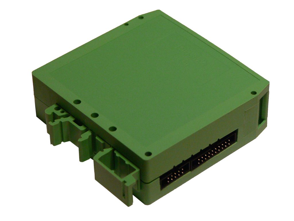
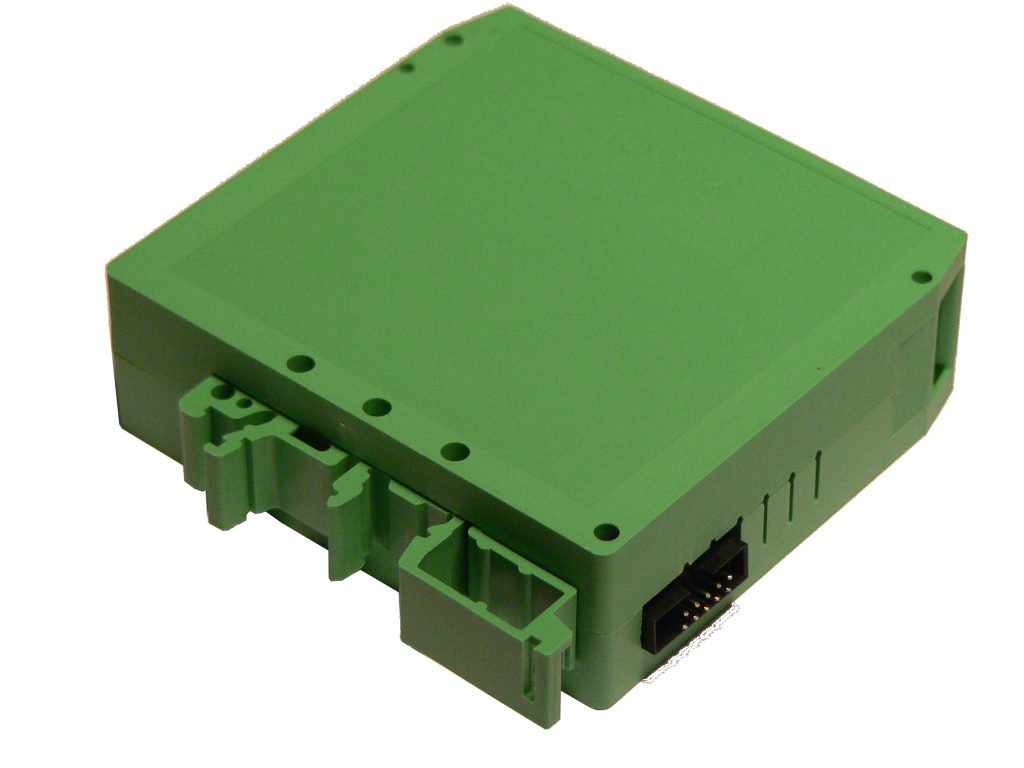
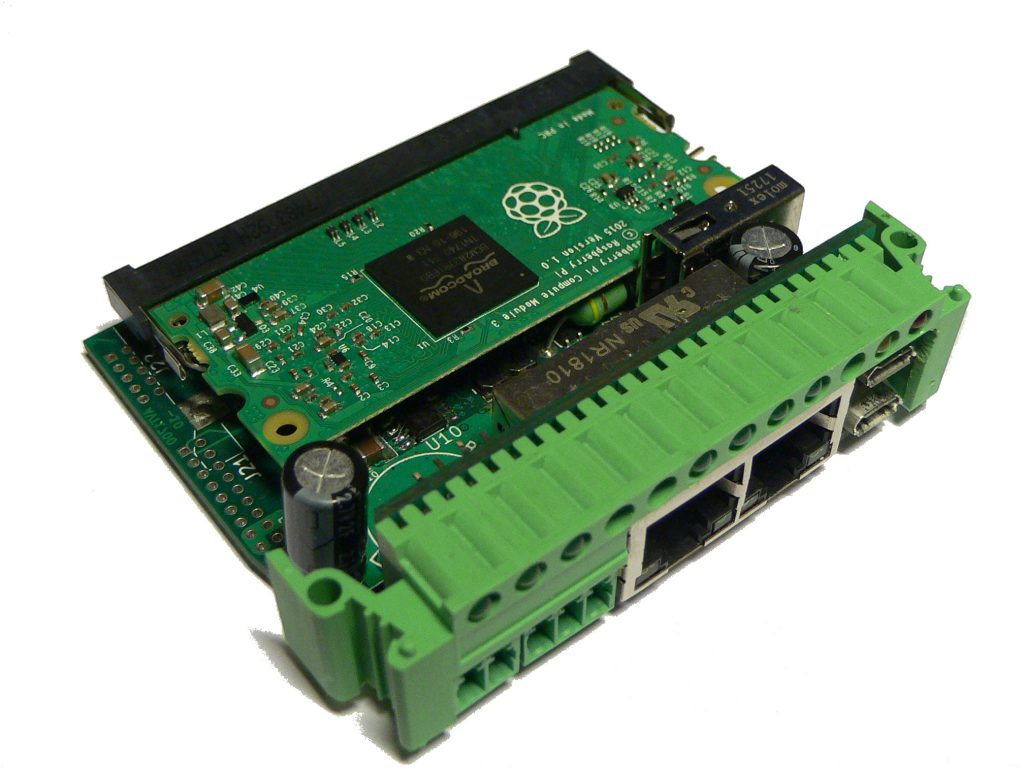
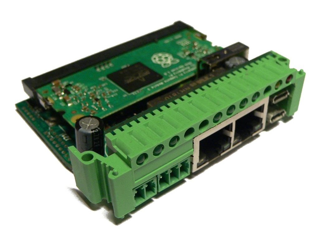
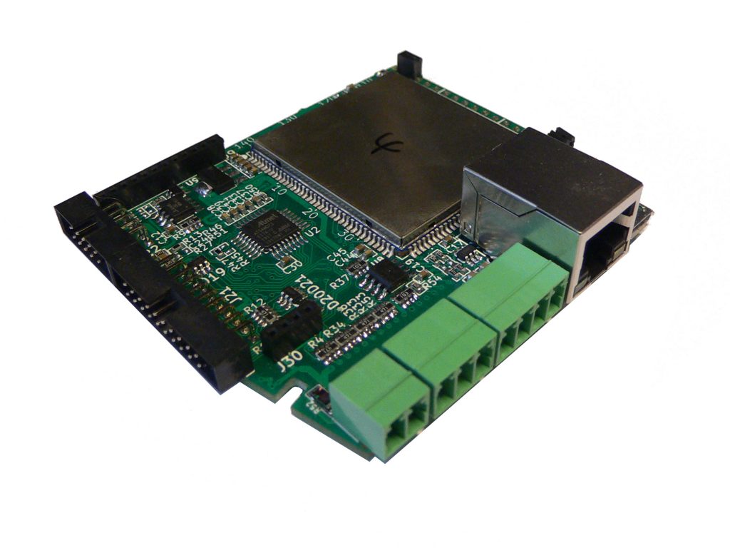
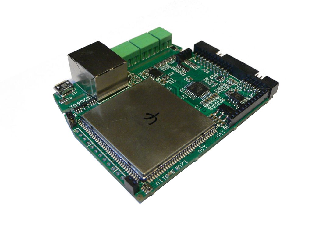
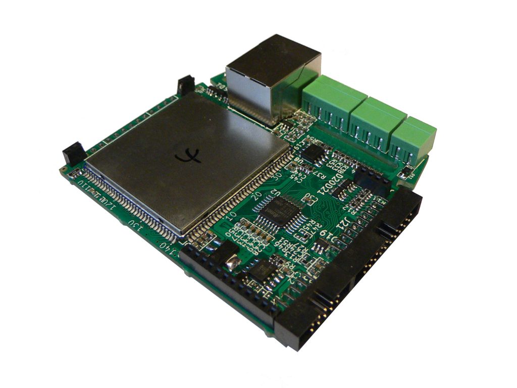
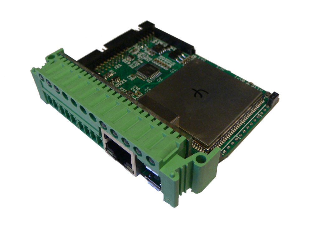
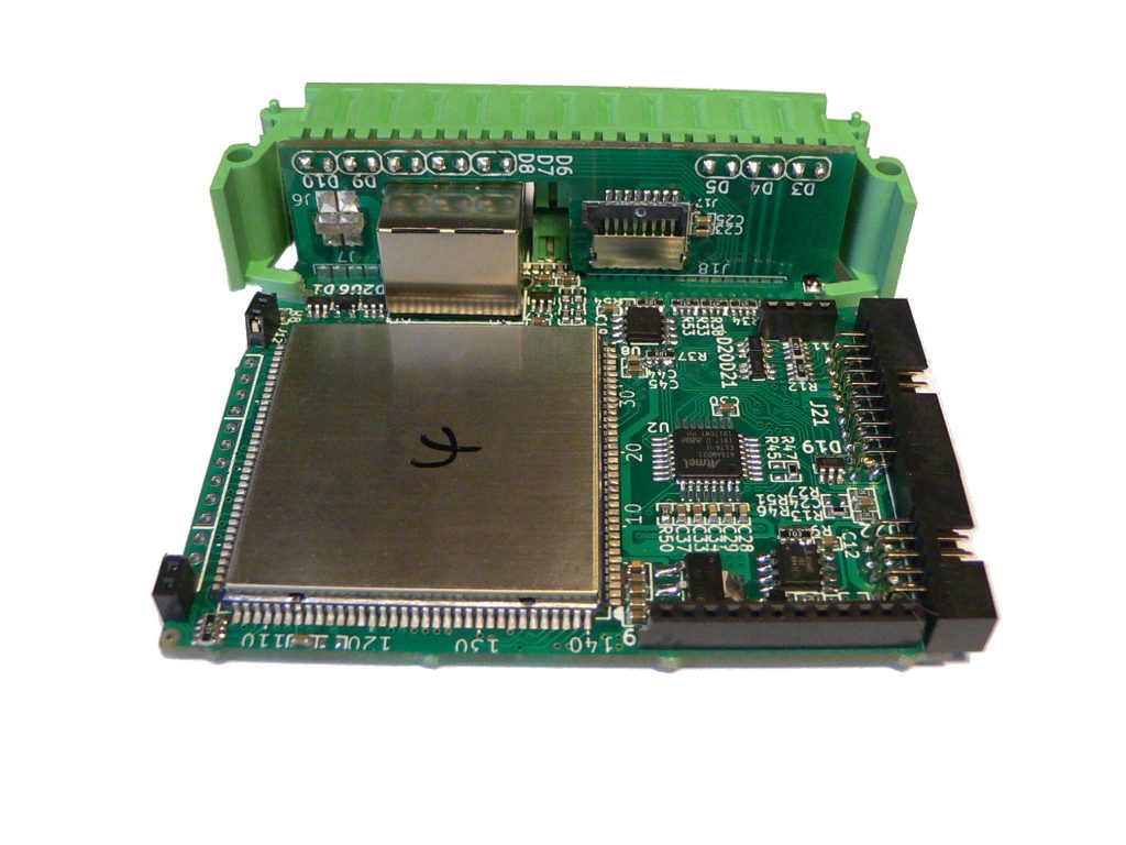
Version 2 of CPU2 has slightly more complicated construction than it’s first incarnation. It consists of three PCBs. The base PCB holds connectors, Linux MPU module, auxiliary CPU, etc.

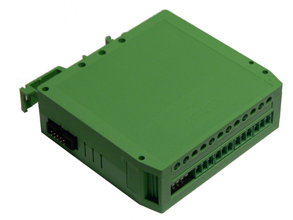
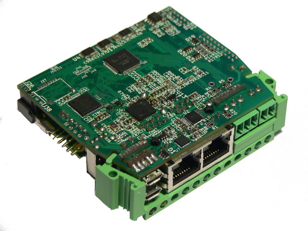
The second PCB holds LEDs, second USB and SD card slot. This slot is in a position where an inserted SD card is precisely fixed by the upper part of the enclosure (so the SD card can not jump off).

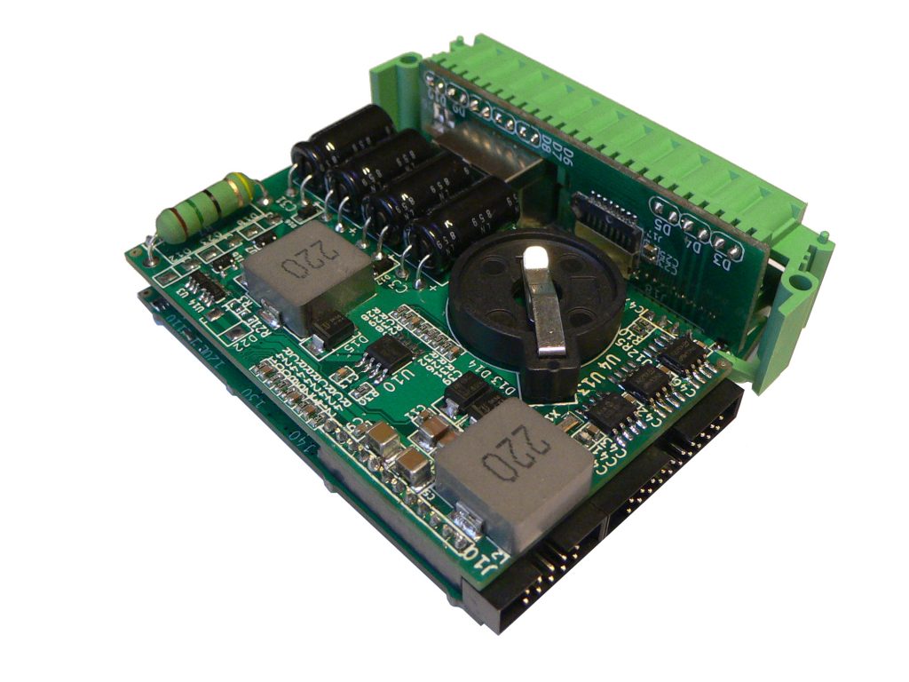
And finally there is the third PCB, which holds the power supply, backup capacitors (that allow the module to continue running for at least 10 seconds after the power disconnects), RTC with battery holder and two EEPROMs (one working and one backup).

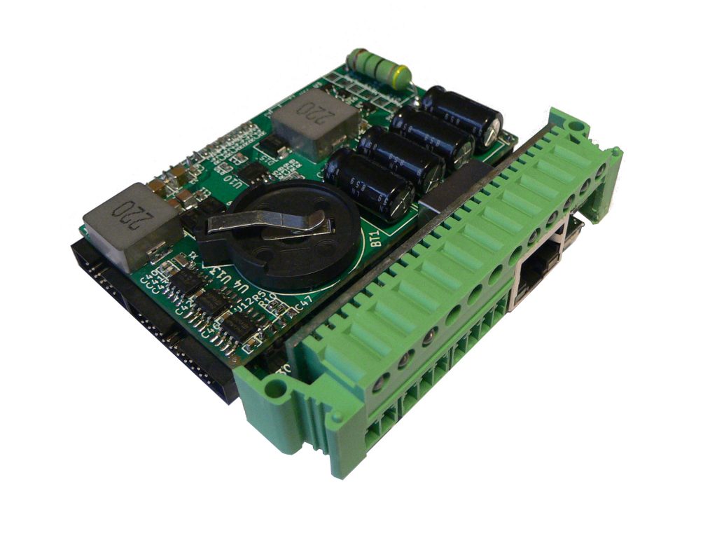
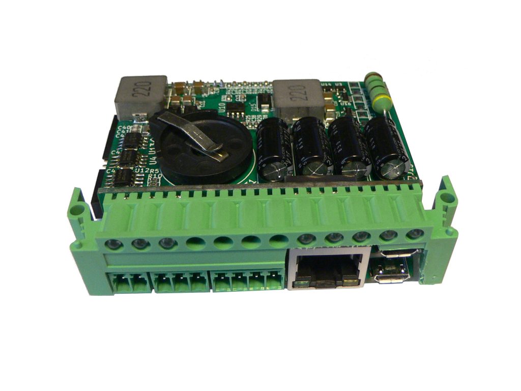
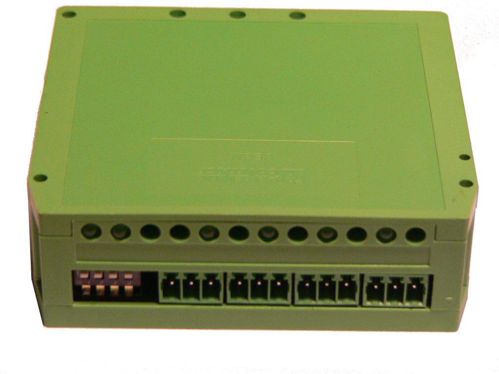
Front connectors are unchanged. From the left: power connector 24V, RS485 non-insulated, two auxiliary inputs with power output, Ethernet connector and finally two micro USBs. The first USB is directly connected to the i.MX 6 USB and can either function as a Host or as a Device. The second USB is connected to auxiliary CPU and normally is used as a UART-USB convertor for Linux system console. But with one smart option – console can be turner off, switched to read only mode (just output from Linux) or used as read/write. This USB is also used to parametrize functionality of auxiliary CPU, for reading the serial number, changing console behaviour, etc.

Second Linux based module (CPU2)

After some research we found out that iMX6UL(L) MPU is the widest used family for embedded Linux. So we started looking for a nice module with this MPU and finally found MYC-Y6ULX CPU Module (MYIR Tech Limited). You can see: http://www.myirtech.com/list.asp?id=572.

This module is relatively inexpensive, easy to use (no connector, just soldered on PCB). The MPU itself has a lot of communication and also one Ethernet PHY (so you need only a connector with magnetics).

Size of the module is suitable for selected enclosure.

The pictures above show the complete enclosure. It has DIN Rail holder (removable) and positions for 12 LEDs. The material of this enclosure is of good quality and it can be relatively well machined (holes).

This module has one Ethernet (directly from MPU module) on the front side, non-isolated RS485 line, power supply 24V +- 10% and 2 auxiliary inputs (for contacts).

The module also has a 10 pin connector (flat cable) for expansion units (non-insulated RS485 and power supply). And it has extra 20 pin extension connector (also flat cable) for custom boards (USB line, 8x GPIO, power supply).

First expansion module (4IG)

Code name 4IG means 4 channel current module with galvanic insulation between channels (and system too). It has internal power supply 24V / 20 mA for current loop sensors (easy to install).

Each channel has 3 terminals – 24V, input and ground. This makes it easy to connect both active and passive sensors.

Communication and power inputs use a 10 pin connector (flat cable) on the bottom of the enclosure.

We were thinking about using several communication protocols and finally decided to use the well known (but not the best) MODBUS RTU protocol.

Every bus oriented connection (as is the case of RS485) requires every connected device to have it’s unique address. A 4-position DIP switch on the bottom of the front side can be used to assign one.

The DIP switch is low profile, right angle. But easily accessed. MODBUS RTU accepts address range from 1 to 250, so value 0 on the switch assigns address 16.

The module has 2 system LEDs (module state and RS485 communication signalization) just above the DIP switch and one LED for each channel.

First Linux based CPU module (CPU1)

Everybody (or nearly everybody) knows Raspberry PI. A lot of people also know Compute module (version CM3). It looks nice, has a lot of processing power, good price, …. so we started the project with this module.

Raspberry CM3 module fits nicely into the selected box (DIN Rail enclosure).

However during the development it turned out electrical connection is really complicated because the CM3 module lacks connections that are standard for industrial use. The module only has a USB port and 2 UARTs. Also this solution required quite a large amount of external components that made the design of base PCB rather complicated. Because of these shortcomings only the functional prototypes were created, development was paused and no production stage devices exist as of now.

Since most use cases do not require the Linux module to be so powerful and focus more on cost-effectivity, subsequent designs are based on different platforms. In case a need for a powerful device based on a platform with strong software and community support arises the designs can be easily adapted to use the latest CM3+ modules and completed.